Content from Introduction
Last updated on 2024-12-31 | Edit this page
Photogrammetry is a technique also known as Structure from Motion (SfM).
Both terms are used to refer to the computing process of estimating the 3D structure of a scene from a set of 2D raster images. A photogrammetry software receives as an input a set of raster images of an object or environment and outputs a 3D model.
Definition
Defined by the American Society for Photogrammetry and Remote Sensing, photogrammetry is the practice of gathering reliable data about physical objects and environments through the recording, measurement, and interpretation of photographic images.
Photogrammetry is a highly favoured technique for documenting the shape and appearance of cultural heritage objects due to its cost-effectiveness.
Essentially, it entails taking 2D photos with a camera and using specialised software to create a 3D model.
This process involves the software initially identifying features in the images, followed by matching these features, and finally reconstructing the 3D object, with or without colour.
How does it do it?
The underlying technology is more familiar than you might think! It is based on the same principles that the ones used by our vision system to perceive the 3-dimensional world.
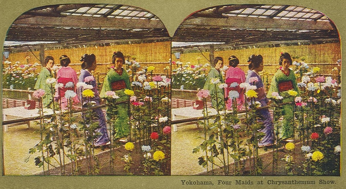
Because of this principle, analogue photographers in the 19th century were already producing stereoscopic and photogrammetric sets of images of many subjects1.
Does it work for everything?
There is no restriction on the scale at which photogrammetry operates.
As such, photogrammetry is performed at a variety of ranges, from microscopic images to aerial or space images.
Be aware that it does not mean it can be applied to every object. There are some restrictions for deploying this technique. For instance, it does not work well with transparent or reflective, shiny objects. Neither does it work well with objects that move constantly, like a live animal or a dress worn by someone.
While photogrammetry may not be ideal for reflective, transparent, and moving objects, there are other solutions to address such issues.
Sometimes, this includes coating an object with powder-like sprays or accessing specialised dome-shape equipment that captures the interaction of light with an object so that this can be replicated in the 3D model.
Heritage Applications
Photogrammetry can be easily deployed with basic equipment, including digital cameras and there is a variety of software ranging from free to professional with costly fees.
Thus, it can fit different project budgets and can be deployed for research, but also for archiving and for allowing wider access.
Archaeological sites
Skara Brae, Orkney by Historic Environment Scotland on Sketchfab
Museum artefacts
Architecture
Kuelap - Construcción by Ministerio de Cultura Perú on Sketchfab
Natural history
Textiles
Pink and green Spanish dress by Santa Cruz Museum of Art and History on Sketchfab
Challenge
List the objects and environments which are relevant to your own projects.
Search in SketchFab whether 3D models of these objects are available.
Reflect which might be suitable to test with photogrammetry.
Content from Process Overview
Last updated on 2024-12-31 | Edit this page
To generate a photogrammetric model, we might choose to overlook the concepts and formulas utilised within the software to produce such a model.
Yet, understanding how the software works can be highly beneficial. Such understanding enables us to evaluate the feasibility of successfully acquiring objects and identify strategies to enhance our chances of success.
Basic steps
The basic steps of photogrammetric processing are:
- Feature detection
- Feature matching
- Structure reconstruction
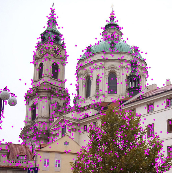
Feature detection
Features are “interest points” or “key points” in an image.
The goal of this step is to find points which are repeatable and distinctive.
Corners and other distinctive patterns in the image are obvious features to consider.
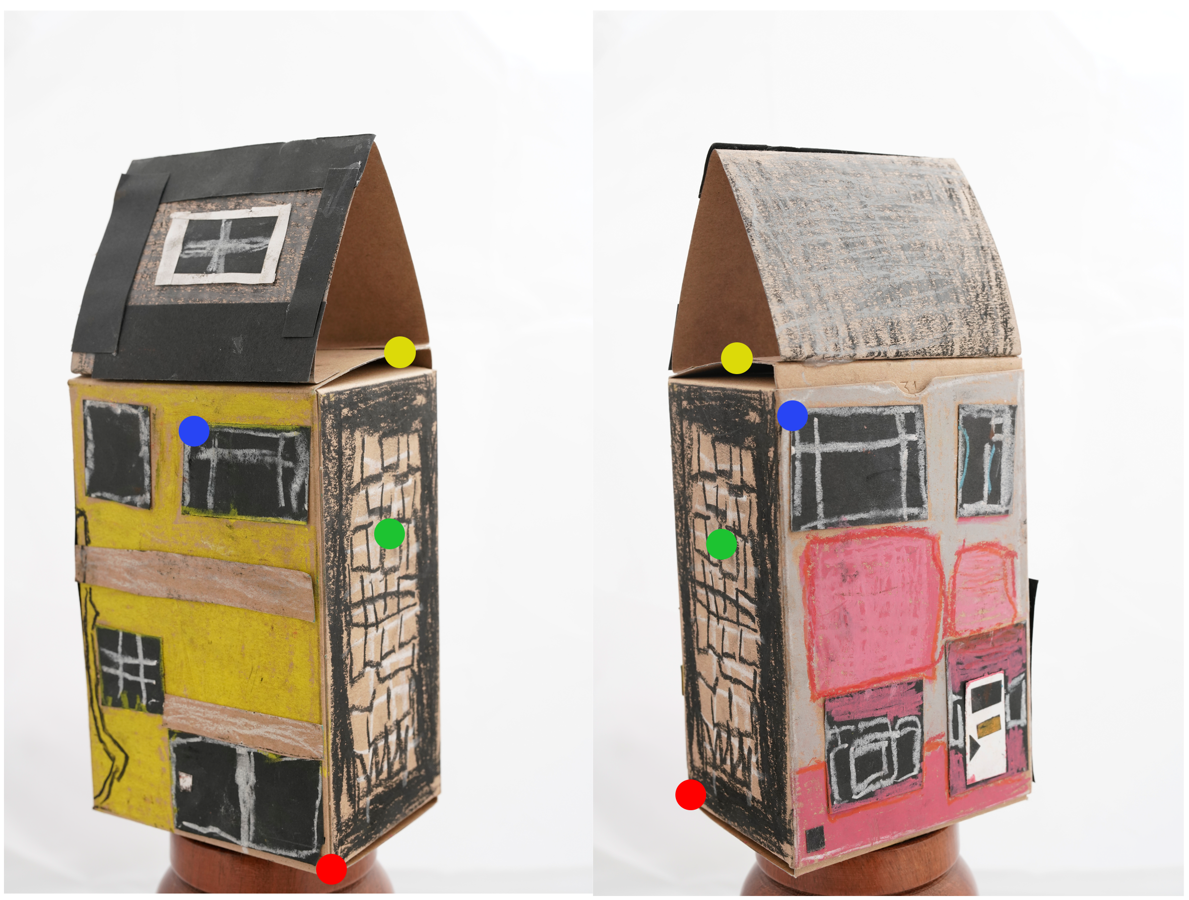
Challenge: Try it yourself
Which points would you choose in this image of a building?
Why?
Challenge: Try it yourself
Which points would you choose in this image of a vase?
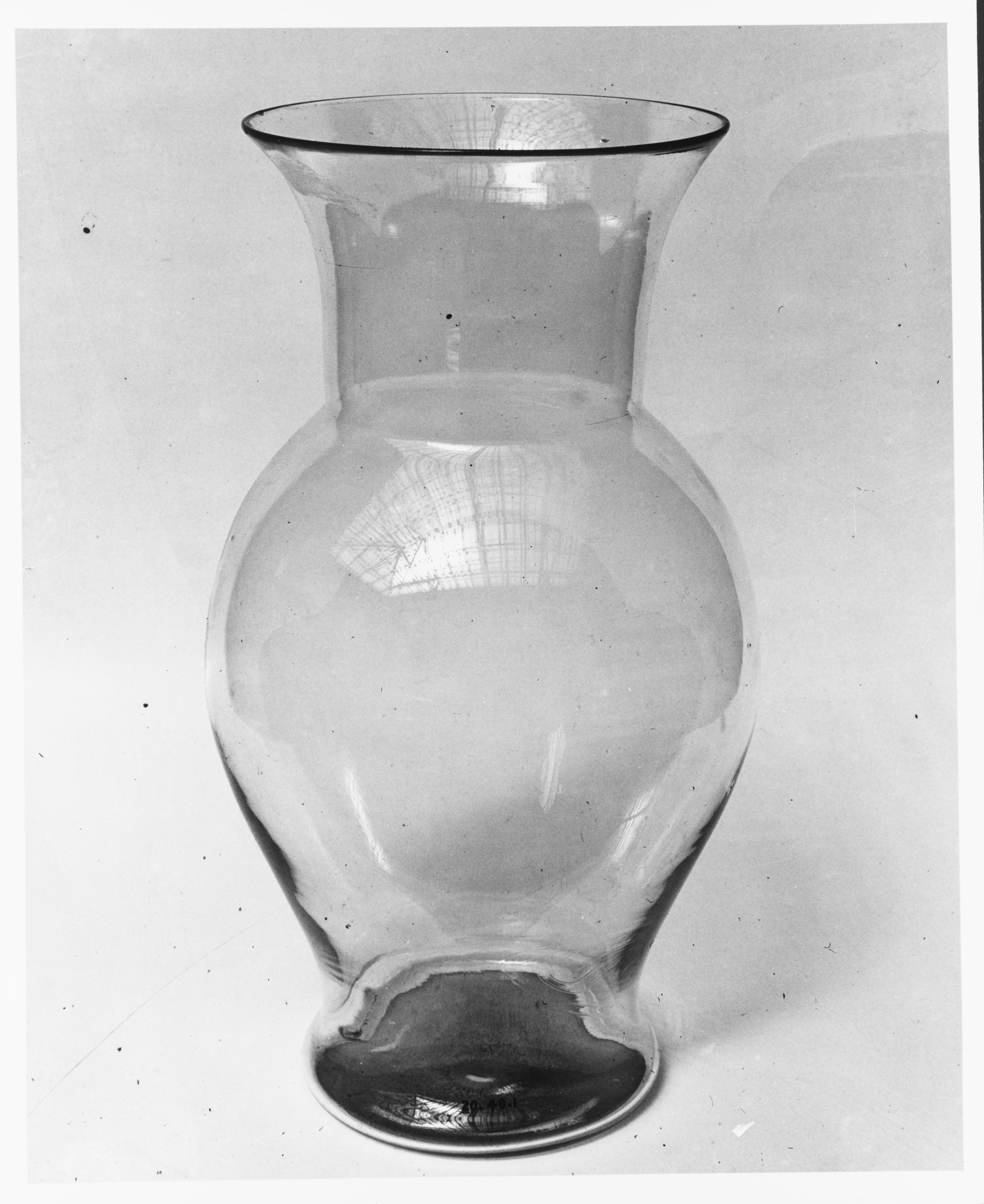
What makes this image different from the one before?
Challenge: Try it yourself
Which points would you choose in this image of a silver mug?
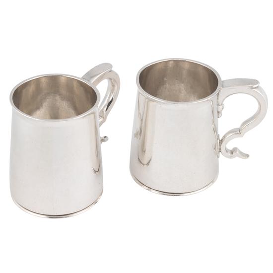
Does this share the same challenges with any of the images above?
Feature matching
The goal of this step is to find correspondences of features across different views.
The software will attempt to match features in two or more images, ideally seeking a reliable outcome. Here we want a reliable result.
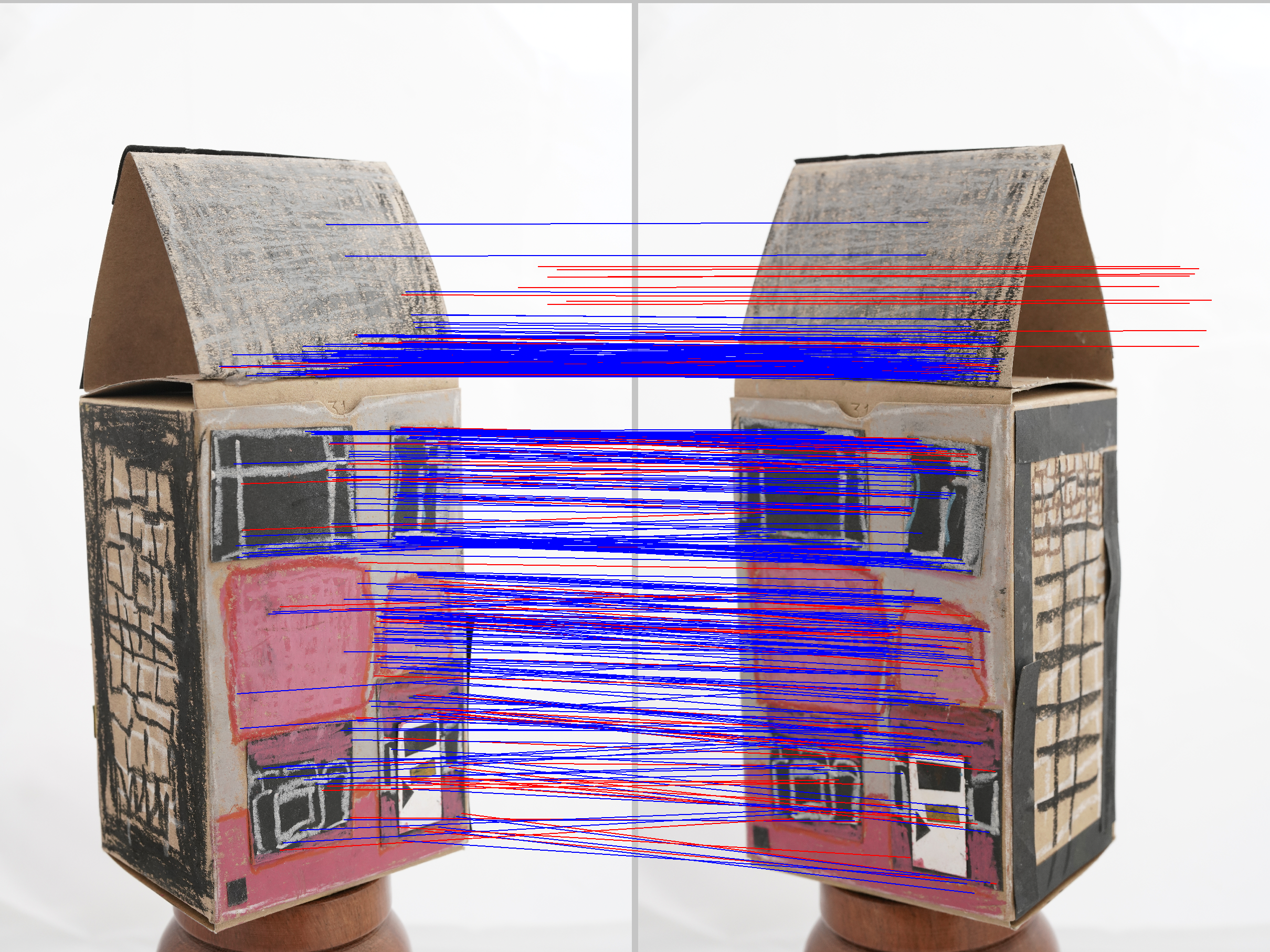
Challenge: Try it yourself
Do the features below correspond with each other?
Structure reconstruction
Taking into account all identified features in a pair of images, the software builds a projection of the points in 3D space by using the camera position.

The scene is incrementally extended by adding new images and triangulating new points.
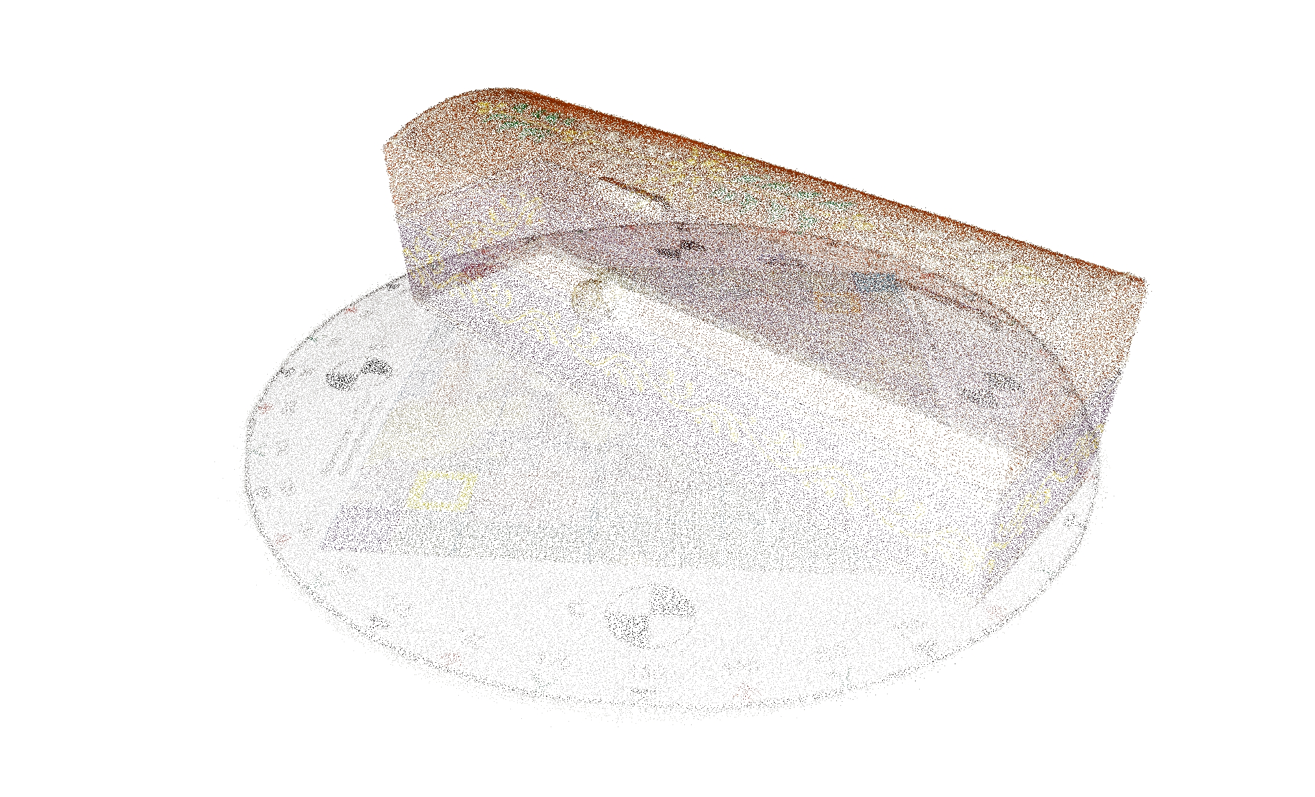
A much denser set of features is produced. The output of this process is a point cloud or a collection of points.
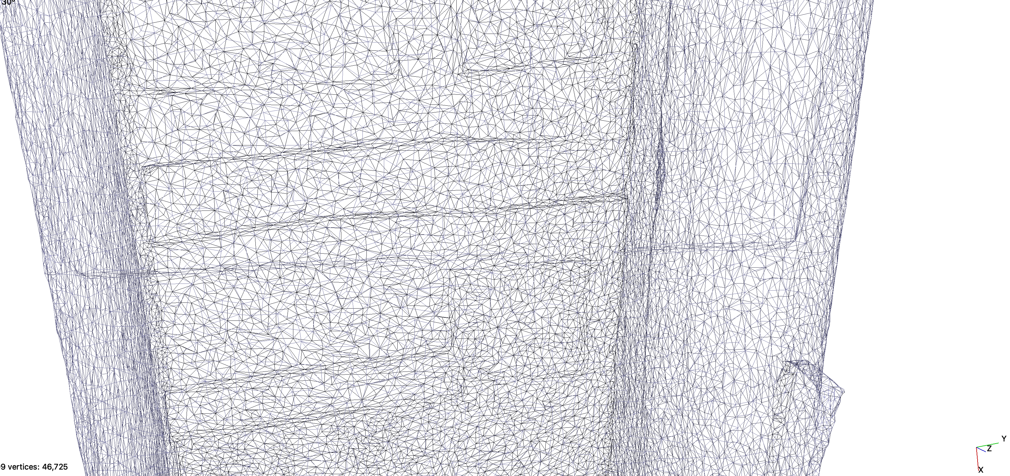
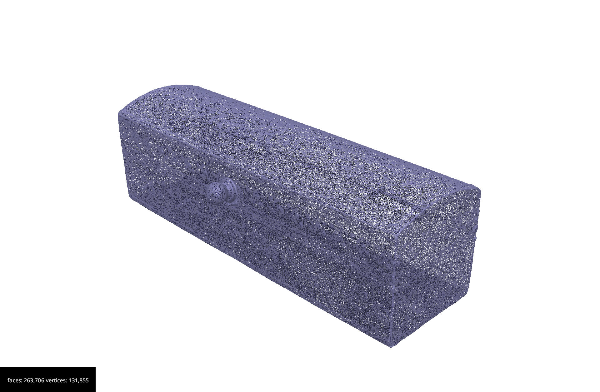
The 3D model is created using what is know as triangulation. This process creates a 3D model with thousands or millions of triangles.
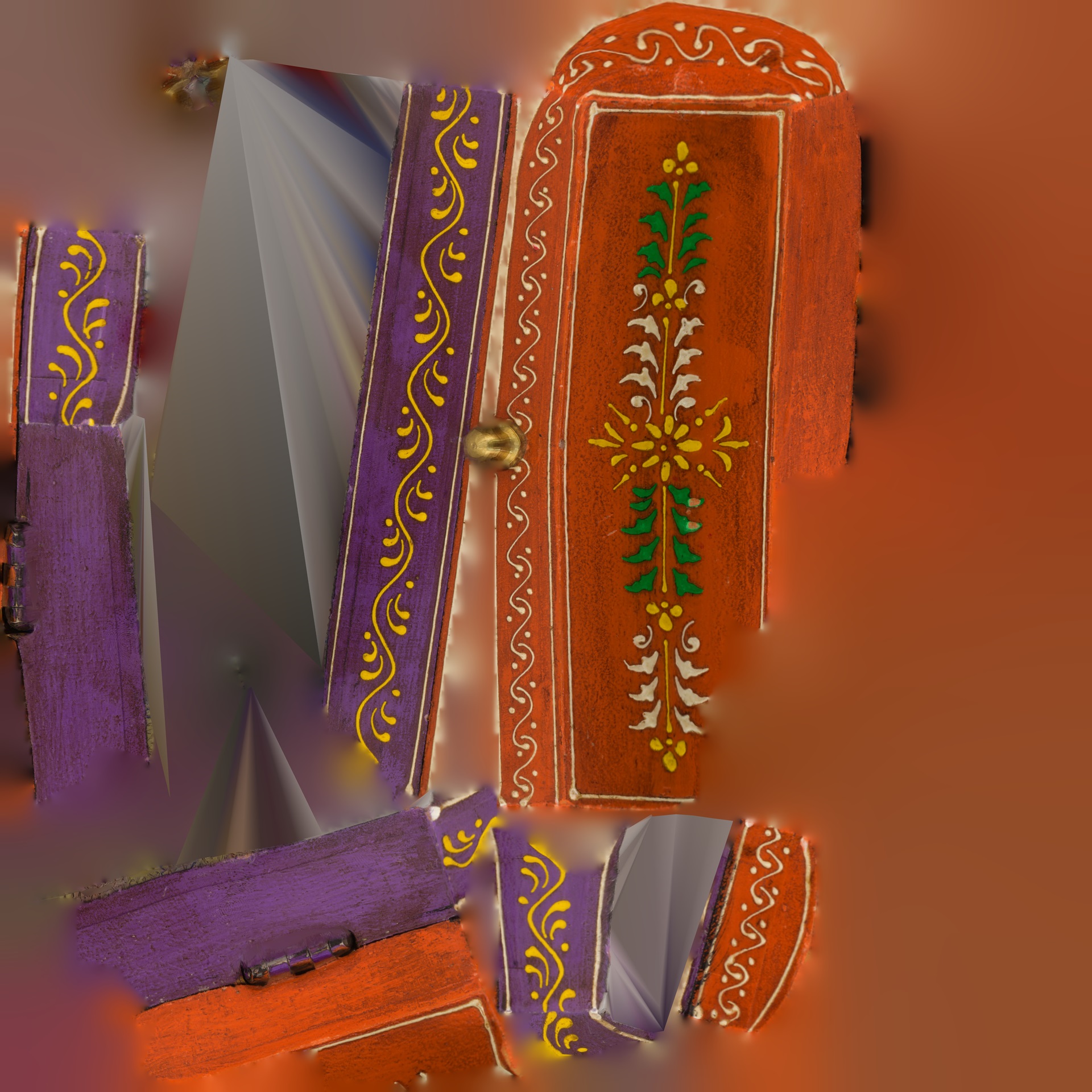
The texture is then mapped to this surface.
Challenge: What does this all mean for me?
Based on what you have seen, reflect on what are the key things to consider when selecting objects for photogrammetry.
Which of the objects you work with would be the best candidates for photogrammetry and which would not be ideal?
Acquisition tips
- Capture images with good texture.
- Avoid completely texture-less, transparent and reflective images. The computer will have difficulty finding and matching features.
- If the scene does not contain enough texture itself, you could place additional background objects, such as posters, newspapers, small objects etc.
Content from Photogrammetry Setup
Last updated on 2024-12-31 | Edit this page
Camera considerations
Some knowledge about digital photography is useful for photogrammetry. In case you do not have advanced skills, it is recommended that at least the following advice should be followed.
Resolution
Preferably shoot in RAW and in maximal resolution. JPG compression creates noise that should be avoided. If JPG images are to be used, then prefer high quality JPG images.
ISO values
ISO values should be the lowest possible as you want clear, sharp images without too much noise. ISO 100 will provide good pictures without much noise but for this you will need a tripod because longer shutter speeds will be required. For hand-held camera you can go up to ISO 800 but this will bring more grain to your pictures.
Aperture
Aperture value (f-number) should be high enough so as to be able to distinguish details without having blurred surfaces. A higher f-number means that you will get a better depth of field. Something between f/8 and f/16 would work well.
Shutter speed
Shutter speed should be fast enough to freeze images and avoid blur that is caused by the movement of the camera. If you are using a tripod you can use slower shutter speeds. The rule here is that anything below (slower) than 1/60 of a second requires a tripod.
Depth of field and focus
You should consider always a large depth of field when possible as good focus especially on the subject is important.

Be careful to have all the important parts of the image in focus. Automatic focus can be used when you are rotating around the object, but you can set focus manually if you are using a turntable.
For a better explanation on how depth of field works in conjunction with aperture, focal length and focus distance you can refer to the websites mentioned below.
Example of settings: f/8, ISO 400, shutter speed 1/30 and if light isn’t enough you can increase ISO to 800 OR lower shutter speed to 1/15 (remember that any shutter speed that is lower than 1/60 requires a tripod). Please note that these are just examples and you should check exposure for every acquisition depending on current light conditions.
More information:
- Cambridge in Color: https://www.cambridgeincolour.com/tutorials/depth-of-field.htm
- Photographylife: https://photographylife.com/what-is-depth-of-field
Before you start
Before embarking on photogrammetry, consider the object you want to digitise and the space available to do this. You might want to ask yourself:
- Does the object has enough texture for the software to find enough features?
- If outdoors, is the building or environment in a busy area with passers by or lots of foliage?
- Will I use natural or artificial or natural light to best illuminate the object?
- What equipment will I need with me if I need to travel to perform the digitisation, what will I have access once I am on site (e.g. power to recharge batteries)?
Overall, the recommendation is to avoid plain and monotonous surfaces. Flat, shiny, transparent, very thin artefacts and textures such as fur, hair won’t be the ideal candidates for photogrammetry.
Moving objects (e.g. leaves of a tree or people walking) are not good candidates either.
Some objects are shinny and the reflections will result in having lots of noise, hence a ‘bad’ model. Adding talc or corn-starch on the surface of the object could be a solution but this cannot be applied on most cultural heritage artefacts.
Significant colour changes or colour designs on a relatively plain surface could provide good reference points and help us to produce a model.
The best candidates are rigid, non-reflective, textured artefacts.
Photographing the object/environment
Good acquisition of images is important in order to have a successful project.
Depending on the type of the object and scene you want to acquire, you might be able to create an optimal setup which can allow you to develop a workflow to provide you with a good 3D model.
Thankfully, there is guidance and best practices, provided by independent bodies and software companies. For example, see the 3D Flow software guidance.
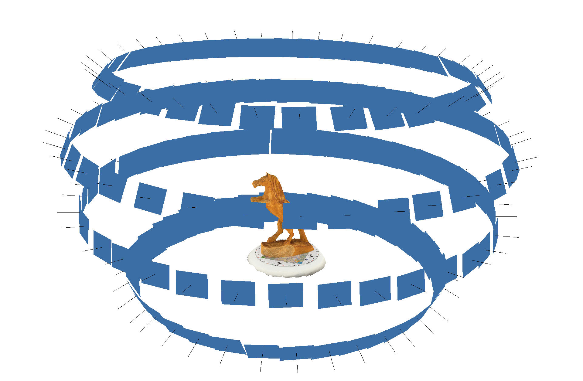
In general, start the acquisition from an angle/view of the object that has many details and is not very plain. Thereafter, you need to take images around the object as shown in the image below.
Overlapping
In all cases you need many overlapping images of the object or environment. When taking images, you need enough overlap between, around 50-60%, to make sure that the software will be able to align the images correctly.
Number of images
20-60 for each 360 acquisition. Remember that it is better to have more images than less. ‘Bad’ images (e.g. blurred, not in focus) can be deleted before processing.
Remember that you should avoid having ‘blind-zones’ and the object should occupy the maximum possible frame area.
Close-up photos are allowed only to capture minor details.


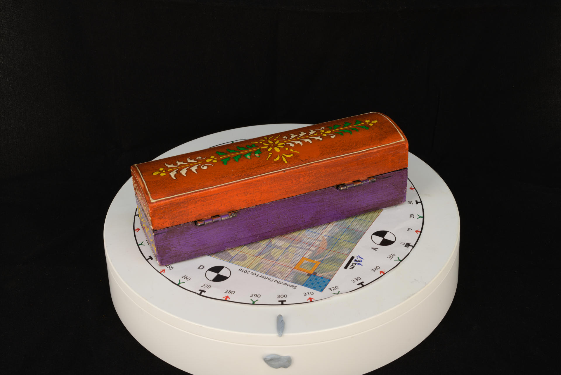
Targets/markers
You can put some markers and targets on/around/underneath the object that you want to acquire to help the software with the aligning process.
To support accurate measurements of 3D data you can also place a calibrated scale image underneath the object (or scale bars around it).
You can use these two images which contain both a texture, as well as a scale image. Follow the instructions, including printing in colour and at 1:1 scale:
Remember that these points should remain in the same position with respect to the object.
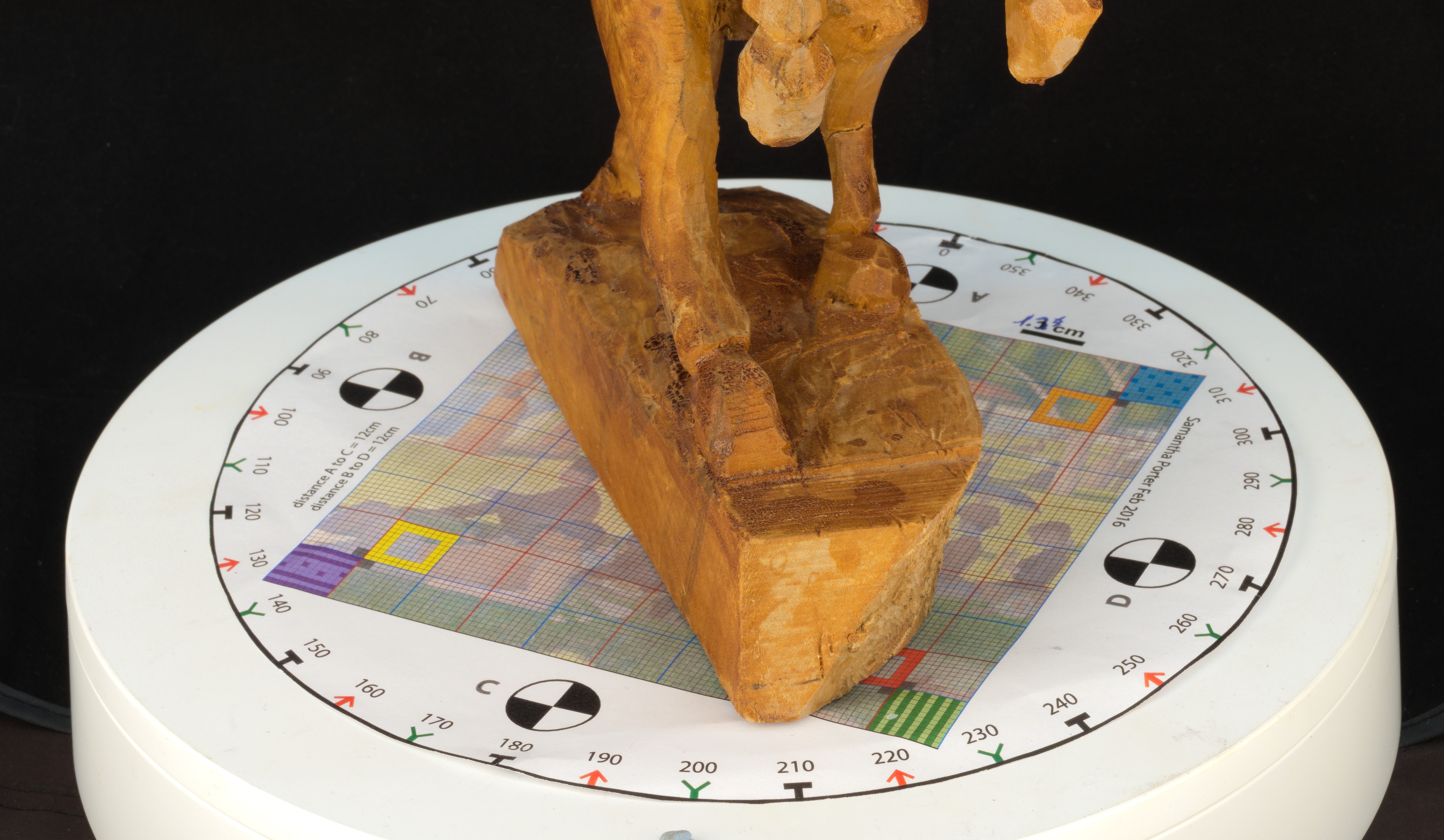
So, if you move with the camera around the object they should remain in the same place (e.g. placed around the object). But if you are using a turntable they should turn along with the object (e.g. placed underneath the object).
Lighting
Good lighting is required and occlusions should be kept to minimum.
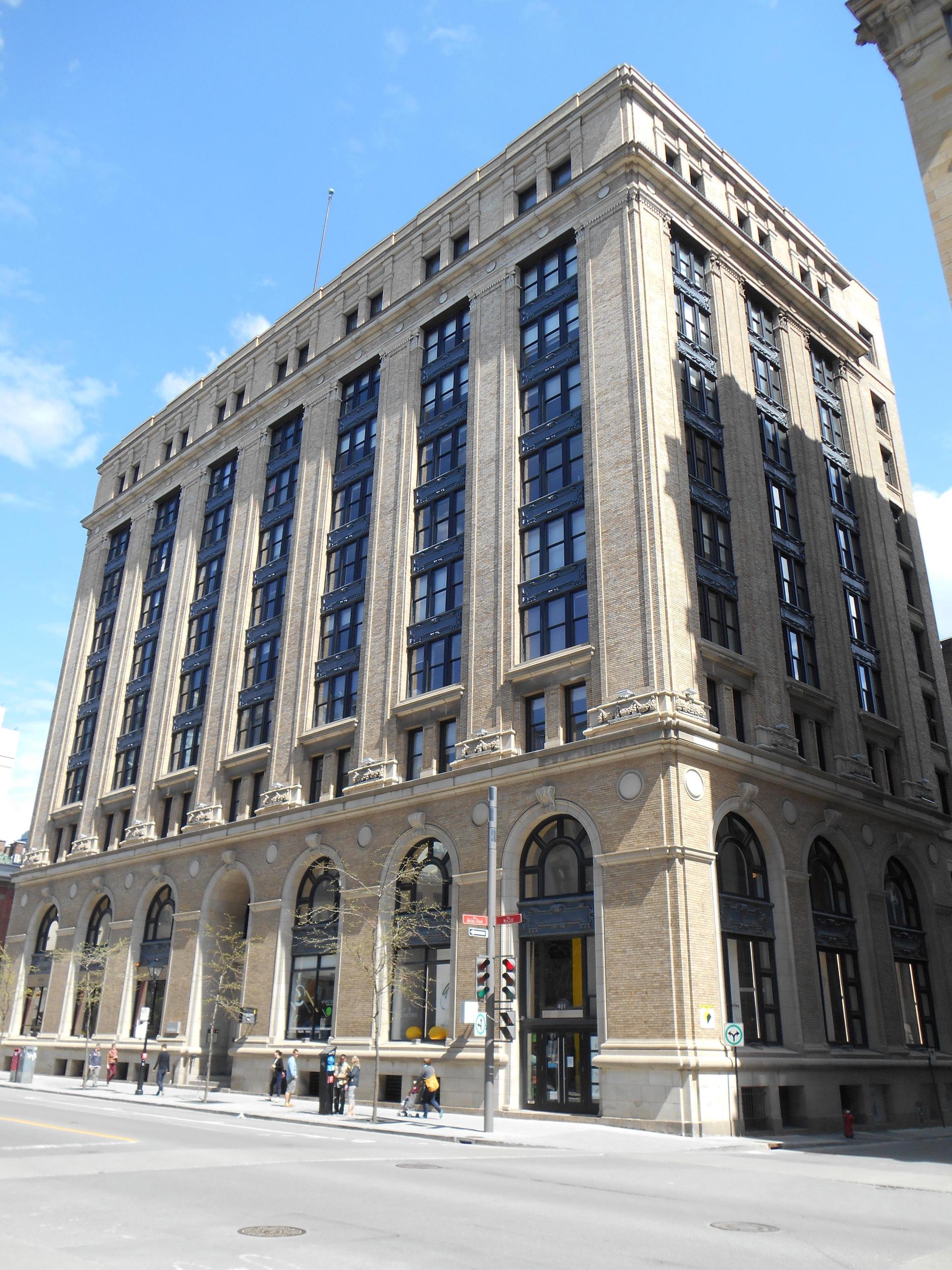
The ideal conditions for an outdoor acquisition require an overcast/cloudy day.
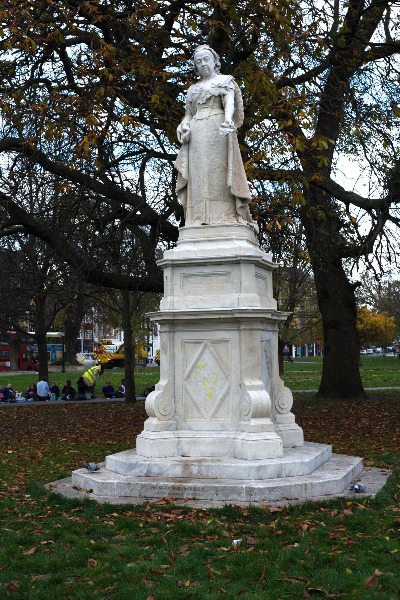
If there is sun that creates shadows, you can use a sheet to shade the object of interest. But for buildings, it might not be possible as illustrated below.

For indoor acquisition, you can use static artificial light. In this case, lights should have the same intensity.
It is better to use diffused light that is projected on every surface of the object equally.
Two light sources can be placed on the sides of the object at an angle of 45 degrees and one can come from the top.
Shadows should be avoided as much as possible (thus you might want to add more light sources, for example one at the back).
Types of setup
There are two different types of setup which you can use depending on the equipment and accesories you have access to. Their difference is whether the camera or the object remains static.
In cases where you cannot touch the object, then you will only have one choice: to move the camera.
In all cases you can create various series of images by varying the height of your camera. For this, you can raise or lower as well as adjust the angle of the camera to take another series of photos.
Static camera / move object
In this setup the camera is going to remain static on a tripod. Ideally you want to control the camera remotely to avoid small movements which can be caused by your hand pushing the trigger.

The object is placed on a turntable. A turntable which is controlled remotely works best. Again, you want to minimise movements caused unintentionally on the object’s position.
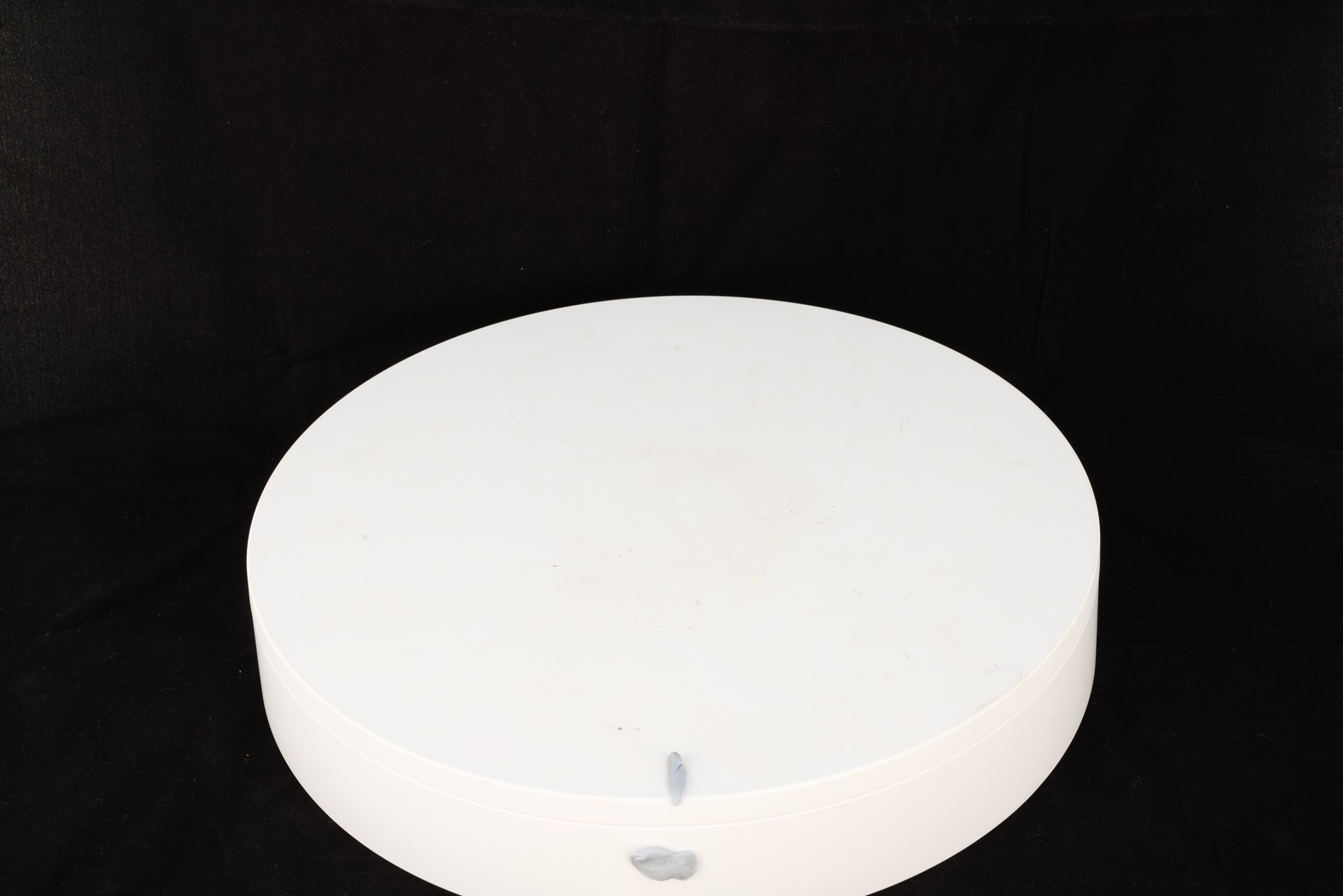
To avoid the software getting confused by the object moving but the background remaining static, you can use a box or cloth as a background.
Black or white background work better as you want to avoid reflections onto the object and alter its colour. Black is always a safe choice, unless the object is dark. In such case, it is best to use a white background.
We will later mask the background, so that the software ignores it. To help with this, take an image of the setup without the object before placing the object. This will later become useful when applying the mask to the images.
If artificial light is used, this should be diffused and should not create shadows.
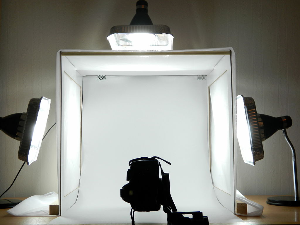

The camera should be placed at a height that allows to see all important features of the artefact (e.g. at an angle of 45 degrees above the object).
When you photograph, rotate the turntable in small increments.
The advantage of this method is that you can have lower ISO and shutter speeds and thus sharper images (especially in indoor environments).
Here you can also find a video of a DIY rig that aims to speed up the process when shooting small and medium objects by Openscan.eu.
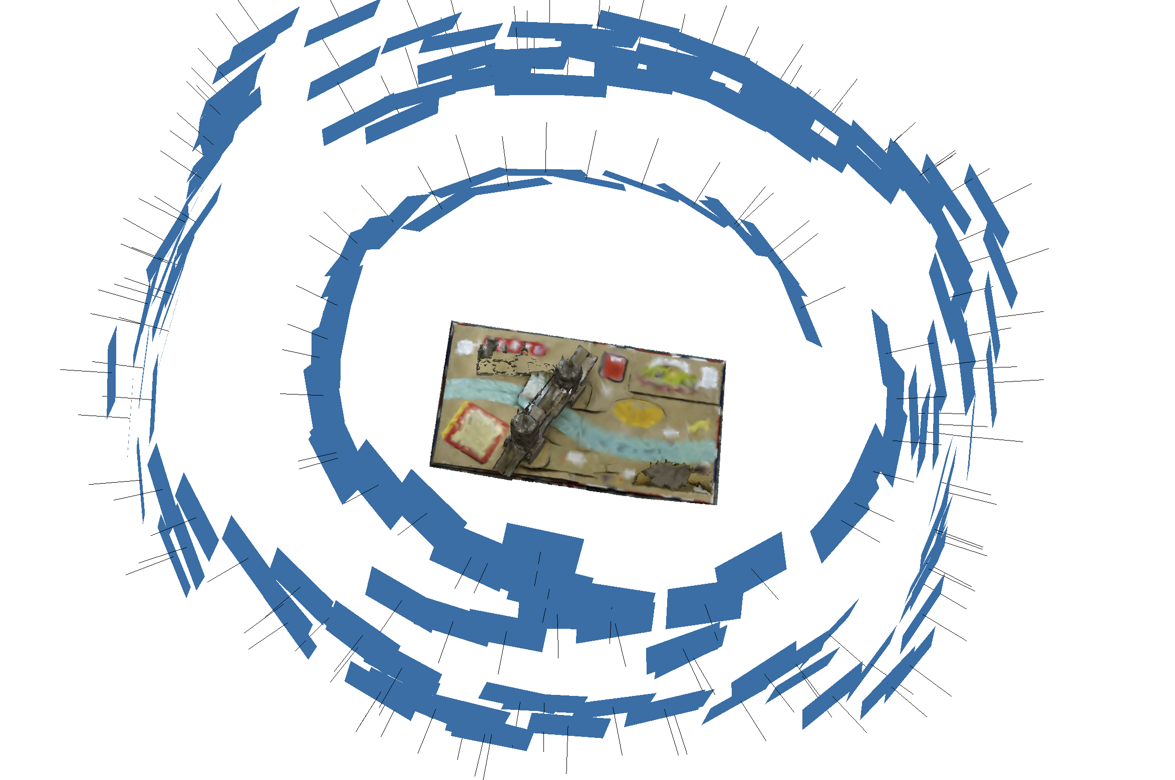
Static object / move camera
The object is placed at the centre and the photographer moves around it taking pictures.

Place the item at a good height so that it is possible to take images from a higher and a lower level.
In case some areas are not that visible, remember to take different pictures of that part from different angles.
The advantage of this method is that it will allow you to acquire larger objects without setting up lights.
Challenge: Taking photos
This activity can be done as a team
Experiment with both setups for photographing one or more objects relevant to your project. When doing this consider the best practices, including:
- Best camera and area setup.
- Adding scale to the images.
- How many series of images you plan to acquire and what is the strategy to achieve this.
Content from Software Workflow
Last updated on 2024-12-31 | Edit this page
Step 1: Preparing the images
Once the photographs have been acquired, the next step is to transfer the images to a PC.
Using a batch processing software, such as Raw Therapee, you can convert the images from the raw file format to a format supported by the photogrammetry software. If you were not shooting using RAW settings, you can skip this step.
Usually, the uncompressed TIFF or TIF file format is a good choice, as it is uncompressed retaining a good quality. JPEGs have a compressed format, and although faster to handle might provide less data for feature recognition.
In any case, you must be sure you choose a format that retains the EXIF information within the file. This is because it contains useful information for the software projecting feature detected into 3D points.
You can check EXIF information online, for example using ExifInfo.org.
For this lesson, we provide images in TIFF and JPEG format.
Step 2: Organising your workspace
We will start by creating a structure to store all the files for your project.
Create a folder using a name which reflects your project.
Good practices include:
ResourceIDofObjectifExistent_NameofObject_DateModelCreatedYY.MM.DDTransfer all images into a folder.
Within this folder, create another folder named images.
Copy the images from the camera into the images folder.
Step 3: Create a 3DF Zephyr project
The following instructions are specific to 3DF Zephyr.
Go to the workflow menu and choose New Project, you will be presented with a “New project wizard window”.
Choose the first box Sparse in order to go through the whole process manually.
Click Next> you will be presented with the “Photos selection page”.
Browse to the folder that contains your images and click Select Folder or select the relevant images if using Single Images.
Click Next>
You will be presented with the “Camera calibration page”.
If you have a separate Exif file for calibrating the camera you can add it here, and you can also manually calibrate your camera in the “Modify Calibration page” otherwise go on and click Next>
Step 4: Importing masks (optional)
Masking allows the software to concentrate in the most important information which is the object you have acquired. It works best when using the “static camera / object moves” setup.
In the “Photos selection page” there is an option to import the mask.
If selected a new option will be presented and a new tool called Masquerade will be available before importing the images.
Within this tool (which is also available from the main interface), it will be possible to generate a Mask to apply to all the images.
The tool is simple to use. To create a mask, you can use an image without any object on the turntable if using such setup.
But you can use a sample image provided in the dataset as a first file.
Step 5: Aligning photos
The next step is to align the photos.
This step will perform the three substeps: feature detection, feature matching and the first stage of the structure reconstruction step.
In the software, you will be presented with the “Camera orientation page”. Keep the general setting and click Next>.
More details about how to manipulate these and the following steps by selecting specific parameters can be found with more detail in the software online manual.
To start the reconstruction, click Run in the “Start reconstruction” page.
You will be presented with the “Reconstruction Successful page”. Click Finish.
Save the project in your project folder.
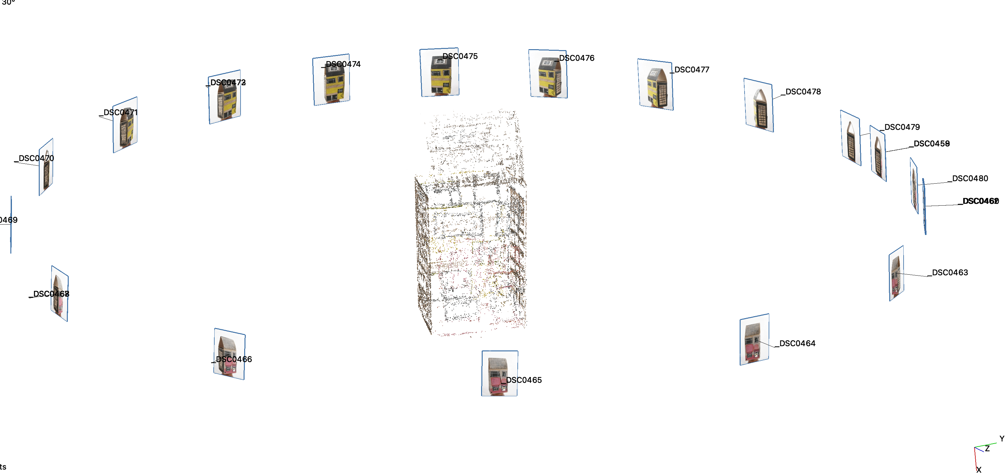
Once the camera orientation phase has been completed, the sparse point cloud will appear in the workspace as well as the oriented cameras identified by blue pyramids.
Now you can familiarise yourself with the navigation of the 3D space and the interface.
For example, go to Scene > Bounding Box > Edit Bounding box and limit the created sparse cloud within the bounding box.
This will speed up the process when creating the final mesh.
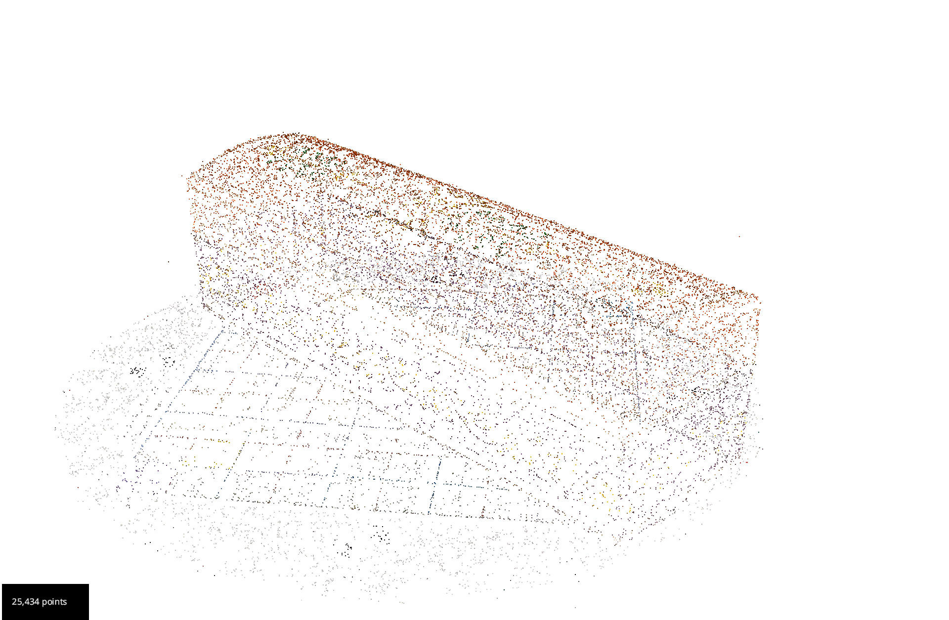
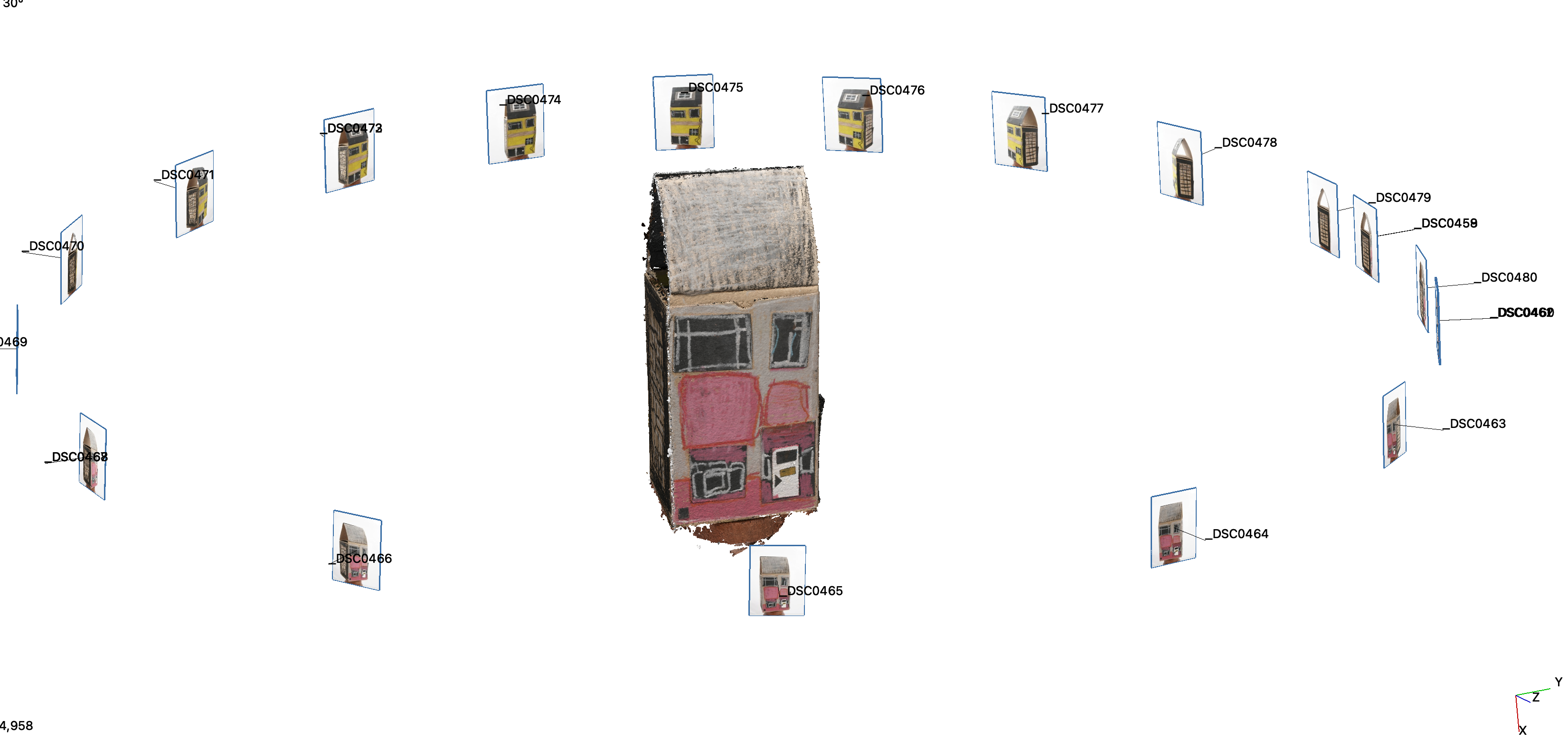
Step 6: Build a dense point cloud
Go to Workflow in the menu and select Advanced > Dense Point Cloud Generation.
You will be presented with the “Dense Point Cloud Generation wizard”. Select All Cameras and click Next>
When presented with the “Dense Point Cloud Creation” page, leave the general settings and click Next>
Click Run on the“Start Densification” page.
When finished, you will see the “Dense Point Cloud generation successful” page. Click Finish.
Save the project.
Step 7: Cleaning the dense cloud
Before trying to create the final mesh, it is useful to delete all the unwanted points. The same bounding box can be used, or the unwanted points can be deleted manually.
Go to the Editing panel on your right and choose By Hand. Choose Poly and Remove.
Start selecting the points that you do not need and once selected deleted them with the delete key.
Once happy save the project.
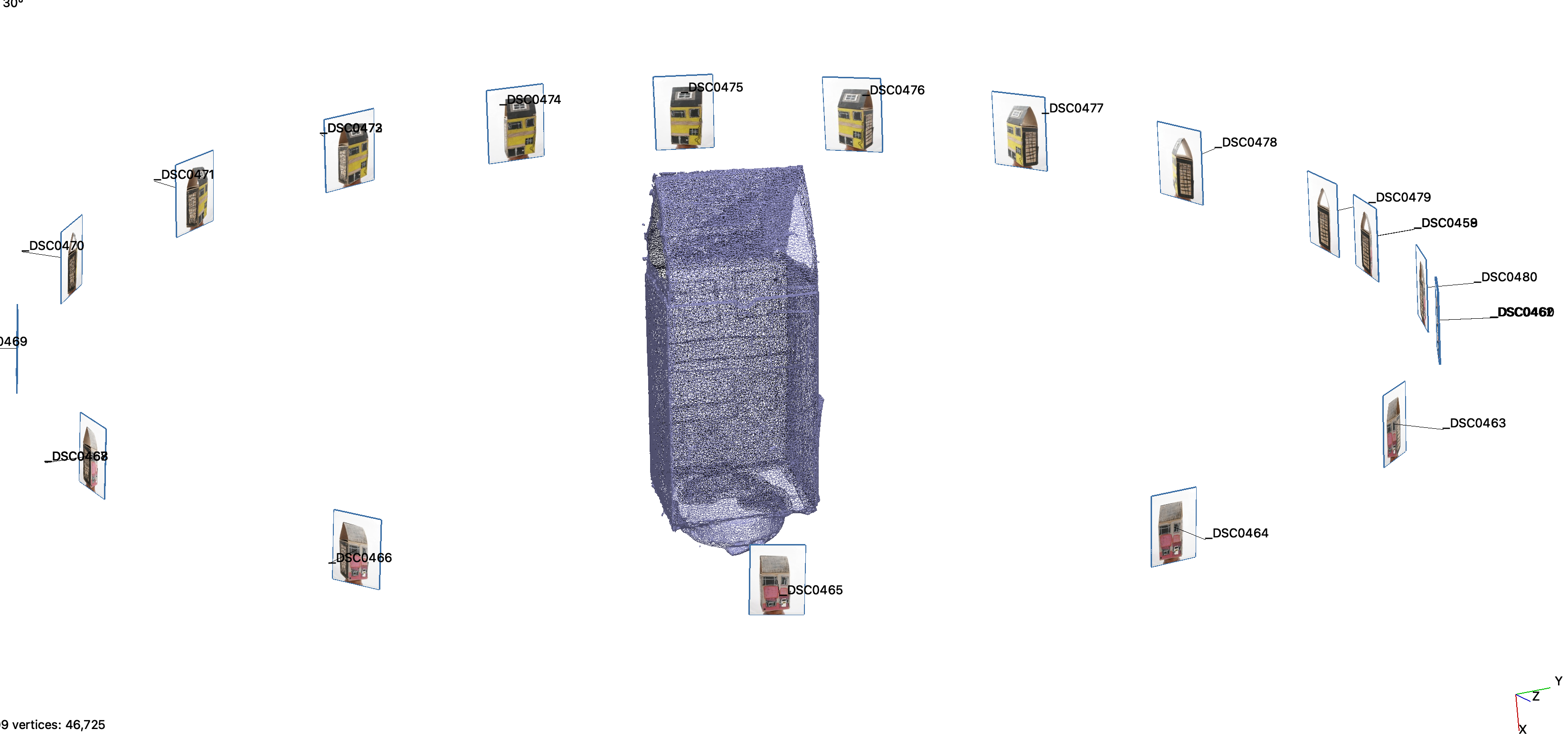
Step 8: Building the 3D model
Go to Workflow in the menu and select Advanced > Mesh Extraction
You will be presented with the “Mesh Generation wizard”.
Select from the drop down the name of your dense point cloud. Select All Cameras and click Next>
Leave the general settings on the “Surface Reconstruction” page and click Next>
Click Run on the“Start Mesh Creation” page.
When finished you will see the “Mesh Creation successful” page. Click Finish. This process will produce a 3D model.
Save the project.
Step 9: Building the raster texture
The final step is to re-project the texture onto the 3D surface.
Go to Workflow in the menu and select Textured Mesh Generation.
You will be presented with the “Textured Mesh Generation wizard”. In the drop down menu select the name of your mesh. Select All Cameras and click Next>
Leave the general settings in the “Texturing” page and click Next>
Click Run on the “Textured Mesh Generation wizard” page.
When finished you will see the “Textured Mesh Generation wizard result” page. Click Finish.
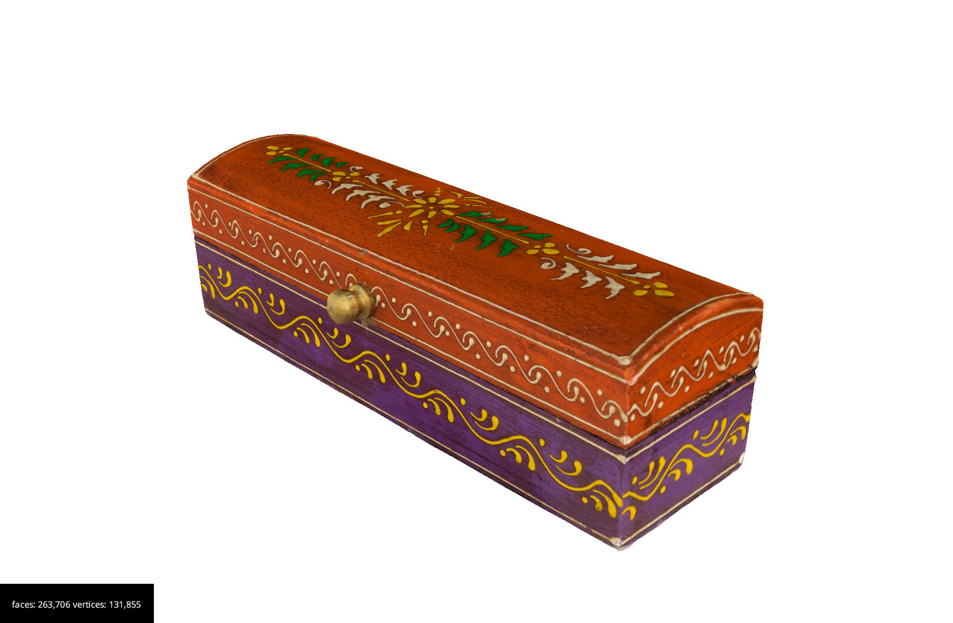
Now you will have a 3D model with the texture.
Save the project.
Step 10: Exporting the 3D model
At this point, we can export the 3D model.
Create another folder called “Exports” within your project folder and save the model in this folder.
It will be useful to export various 3D models at various resolutions. This will allow you to keep a high-resolution 3D model, while having a low-resolution 3D model for sharing and making available on the web.
It is good practice to name your models with information, for example:
ResourceIDofObjectifExistent_NameofObject_DateModelCreatedYY.MM.DD.[highres|medres|lowres]Go to Export in the menu and select Export Textured Mesh.
Select from the drop down, the name of your mesh.
Select from the drop down your preferred format and click Export.
To export the model at a lower resolution select your textured mesh in the right window “Textured Meshes”. Right Click on it and select Clone. A copy of your mesh will be created.
Go to Tools in the menu and select Mesh Filters > Decimation. You will be presented with the “Mesh decimation” window.
Select in the drop down menu the name of your cloned mesh. Select preserve boundaries and Apply Filter.
At this point, we need to regenerate the texture for the lower-resolution mesh. To do so we need to repeat the process above for generating the texture.
Go to Export in the menu and select Export Textured Mesh. Select in the drop down menu the name of your second mesh.
For web sharing GLTF is a good format to use. Select from drop down menu the format .glb or .gltf and click Export.
Challenge: Processing the photos and creating a 3D model
This activity can be done as a team
By using the images you captured during the lesson, use the software to create a 3D model.
Produce two versions: a high-resolution and a low-resolution and save on your PC.
Content from Additional Links
Last updated on 2024-12-31 | Edit this page
3D Flow support links
- Zephyr video tutorials: https://www.3dflow.net/technology/documents/3df-zephyr-tutorials/
- Forum: https://www.3dflow.net/forums/
- Discord: https://www.3dflow.net/forums/