Software Workflow
Last updated on 2024-12-31 | Edit this page
Estimated time: 90 minutes
Step 1: Preparing the images
Once the photographs have been acquired, the next step is to transfer the images to a PC.
Using a batch processing software, such as Raw Therapee, you can convert the images from the raw file format to a format supported by the photogrammetry software. If you were not shooting using RAW settings, you can skip this step.
Usually, the uncompressed TIFF or TIF file format is a good choice, as it is uncompressed retaining a good quality. JPEGs have a compressed format, and although faster to handle might provide less data for feature recognition.
In any case, you must be sure you choose a format that retains the EXIF information within the file. This is because it contains useful information for the software projecting feature detected into 3D points.
You can check EXIF information online, for example using ExifInfo.org.
For this lesson, we provide images in TIFF and JPEG format.
Step 2: Organising your workspace
We will start by creating a structure to store all the files for your project.
Create a folder using a name which reflects your project.
Good practices include:
ResourceIDofObjectifExistent_NameofObject_DateModelCreatedYY.MM.DDTransfer all images into a folder.
Within this folder, create another folder named images.
Copy the images from the camera into the images folder.
Step 3: Create a 3DF Zephyr project
The following instructions are specific to 3DF Zephyr.
Go to the workflow menu and choose New Project, you will be presented with a “New project wizard window”.
Choose the first box Sparse in order to go through the whole process manually.
Click Next> you will be presented with the “Photos selection page”.
Browse to the folder that contains your images and click Select Folder or select the relevant images if using Single Images.
Click Next>
You will be presented with the “Camera calibration page”.
If you have a separate Exif file for calibrating the camera you can add it here, and you can also manually calibrate your camera in the “Modify Calibration page” otherwise go on and click Next>
Step 4: Importing masks (optional)
Masking allows the software to concentrate in the most important information which is the object you have acquired. It works best when using the “static camera / object moves” setup.
In the “Photos selection page” there is an option to import the mask.
If selected a new option will be presented and a new tool called Masquerade will be available before importing the images.
Within this tool (which is also available from the main interface), it will be possible to generate a Mask to apply to all the images.
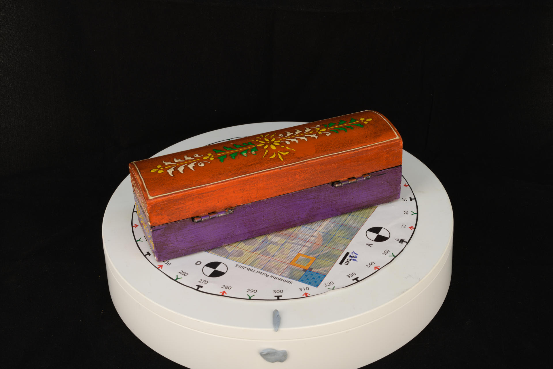
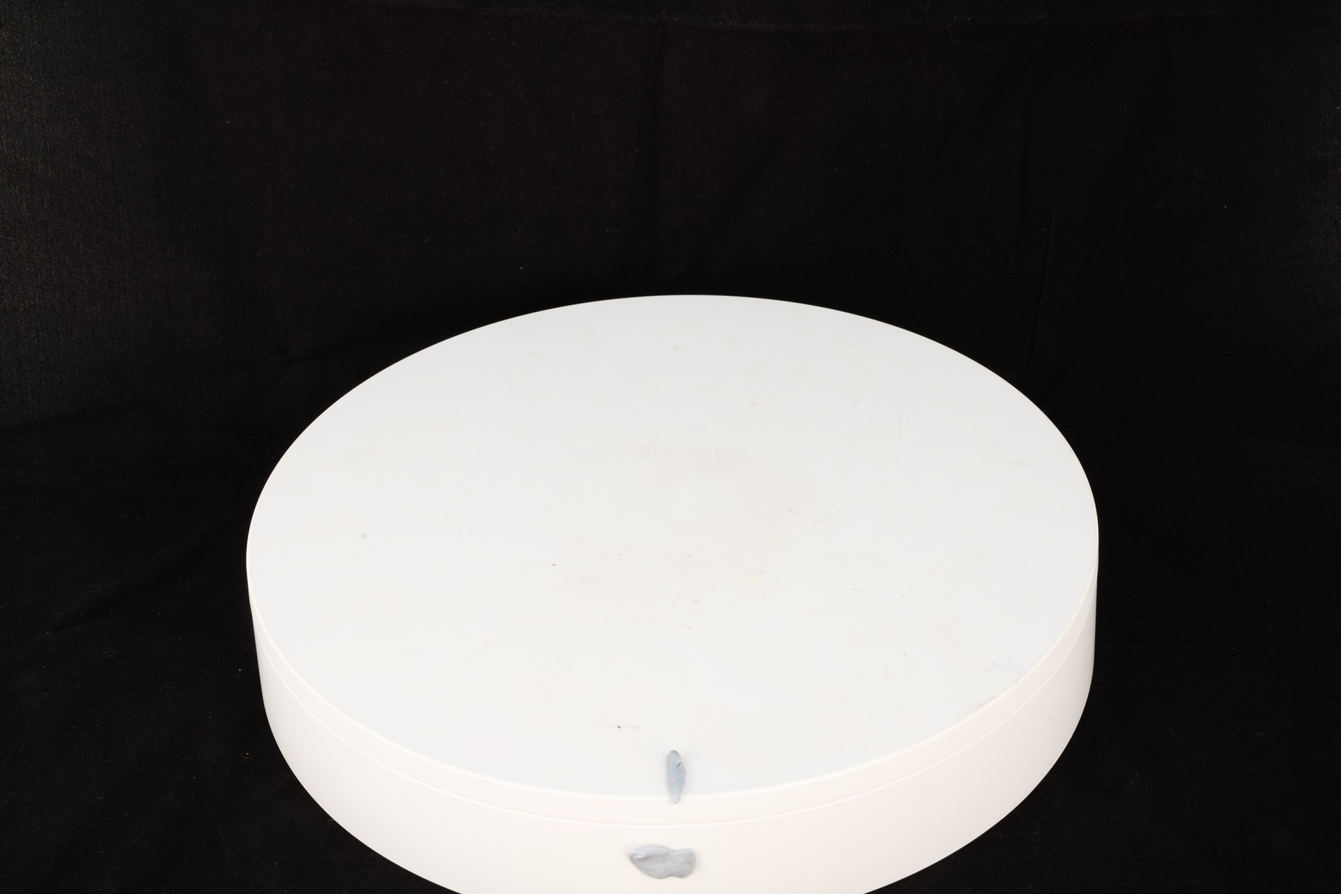
The tool is simple to use. To create a mask, you can use an image without any object on the turntable if using such setup.
But you can use a sample image provided in the dataset as a first file.
Step 5: Aligning photos
The next step is to align the photos.
This step will perform the three substeps: feature detection, feature matching and the first stage of the structure reconstruction step.
In the software, you will be presented with the “Camera orientation page”. Keep the general setting and click Next>.
More details about how to manipulate these and the following steps by selecting specific parameters can be found with more detail in the software online manual.
To start the reconstruction, click Run in the “Start reconstruction” page.
You will be presented with the “Reconstruction Successful page”. Click Finish.
Save the project in your project folder.
Once the camera orientation phase has been completed, the sparse point cloud will appear in the workspace as well as the oriented cameras identified by blue pyramids.
Now you can familiarise yourself with the navigation of the 3D space and the interface.
For example, go to Scene > Bounding Box > Edit Bounding box and limit the created sparse cloud within the bounding box.
This will speed up the process when creating the final mesh.
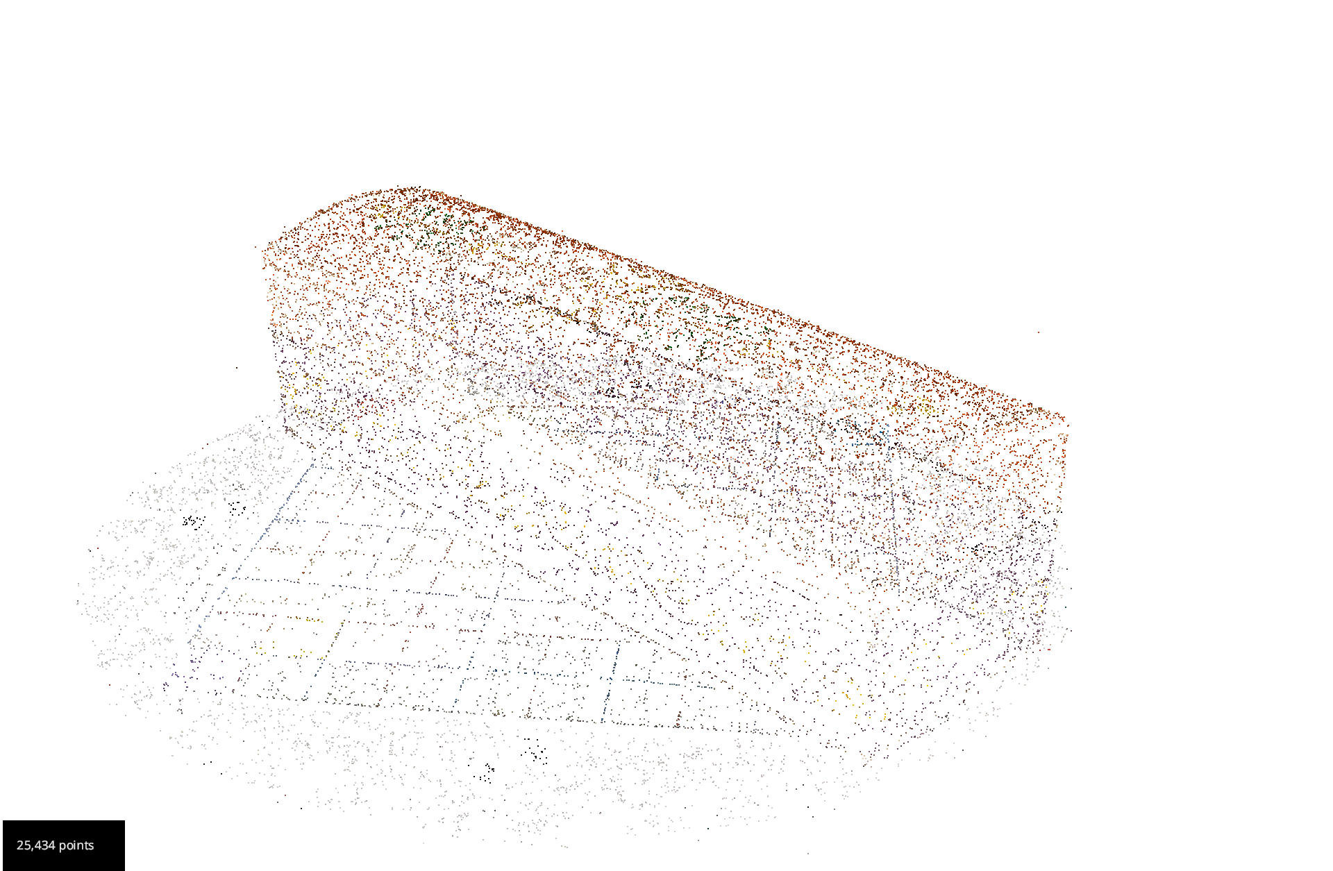
Step 6: Build a dense point cloud
Go to Workflow in the menu and select Advanced > Dense Point Cloud Generation.
You will be presented with the “Dense Point Cloud Generation wizard”. Select All Cameras and click Next>
When presented with the “Dense Point Cloud Creation” page, leave the general settings and click Next>
Click Run on the“Start Densification” page.
When finished, you will see the “Dense Point Cloud generation successful” page. Click Finish.
Save the project.
Step 7: Cleaning the dense cloud
Before trying to create the final mesh, it is useful to delete all the unwanted points. The same bounding box can be used, or the unwanted points can be deleted manually.
Go to the Editing panel on your right and choose By Hand. Choose Poly and Remove.
Start selecting the points that you do not need and once selected deleted them with the delete key.
Once happy save the project.
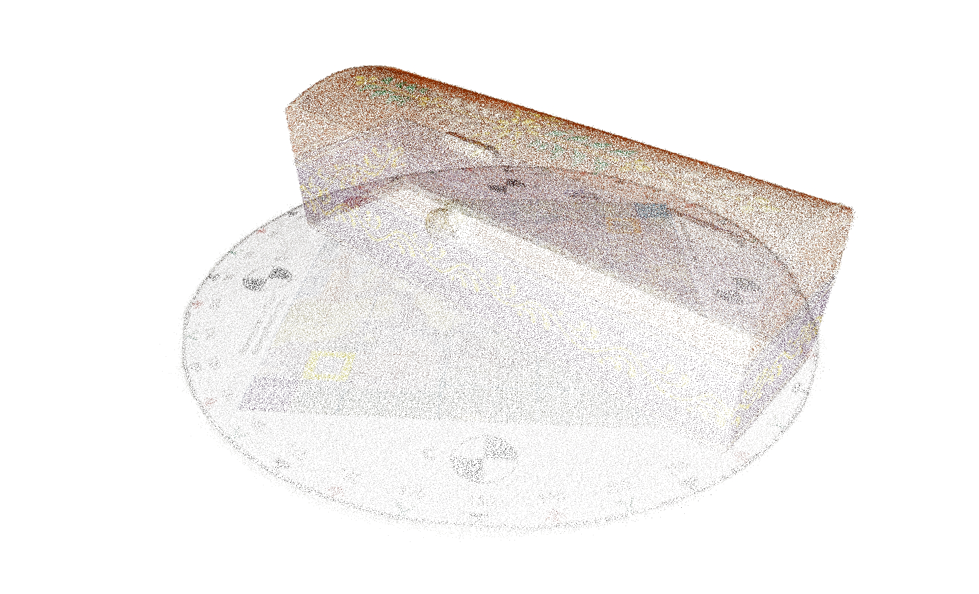
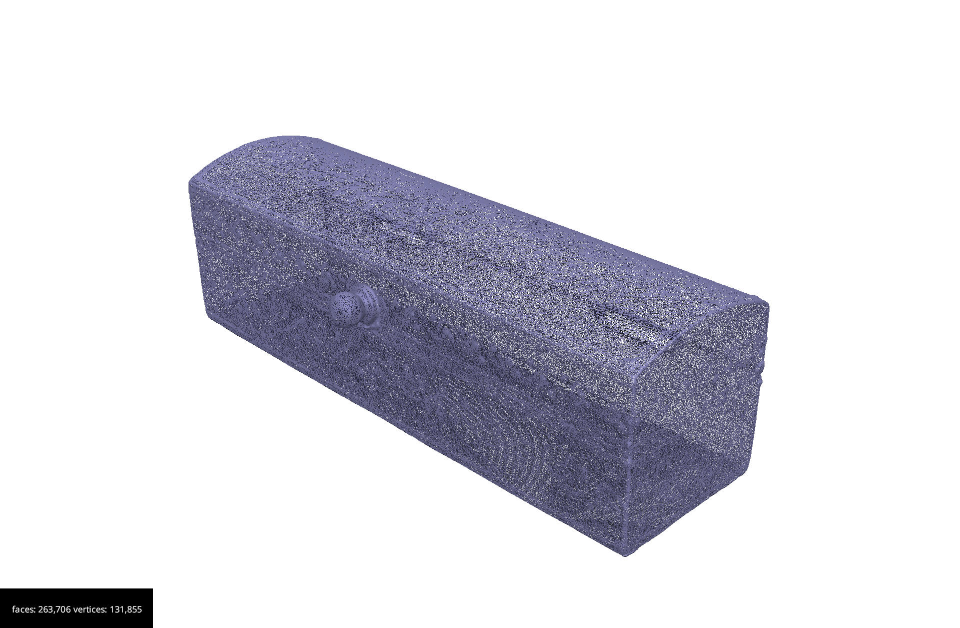
Step 8: Building the 3D model
Go to Workflow in the menu and select Advanced > Mesh Extraction
You will be presented with the “Mesh Generation wizard”.
Select from the drop down the name of your dense point cloud. Select All Cameras and click Next>
Leave the general settings on the “Surface Reconstruction” page and click Next>
Click Run on the“Start Mesh Creation” page.
When finished you will see the “Mesh Creation successful” page. Click Finish. This process will produce a 3D model.
Save the project.
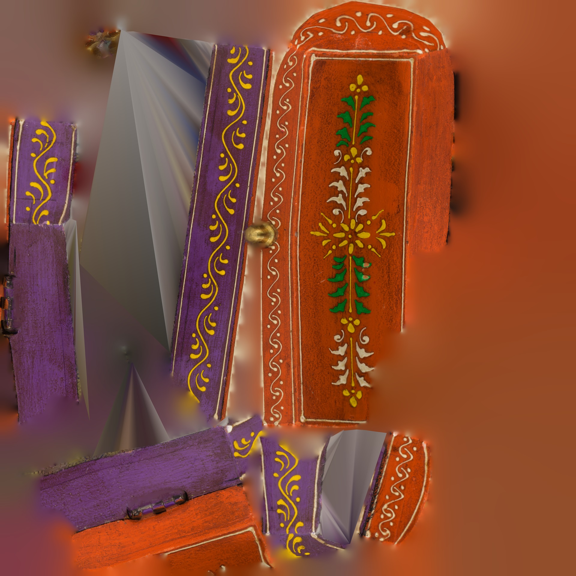
Step 9: Building the raster texture
The final step is to re-project the texture onto the 3D surface.
Go to Workflow in the menu and select Textured Mesh Generation.
You will be presented with the “Textured Mesh Generation wizard”. In the drop down menu select the name of your mesh. Select All Cameras and click Next>
Leave the general settings in the “Texturing” page and click Next>
Click Run on the “Textured Mesh Generation wizard” page.
When finished you will see the “Textured Mesh Generation wizard result” page. Click Finish.
Now you will have a 3D model with the texture.
Save the project.
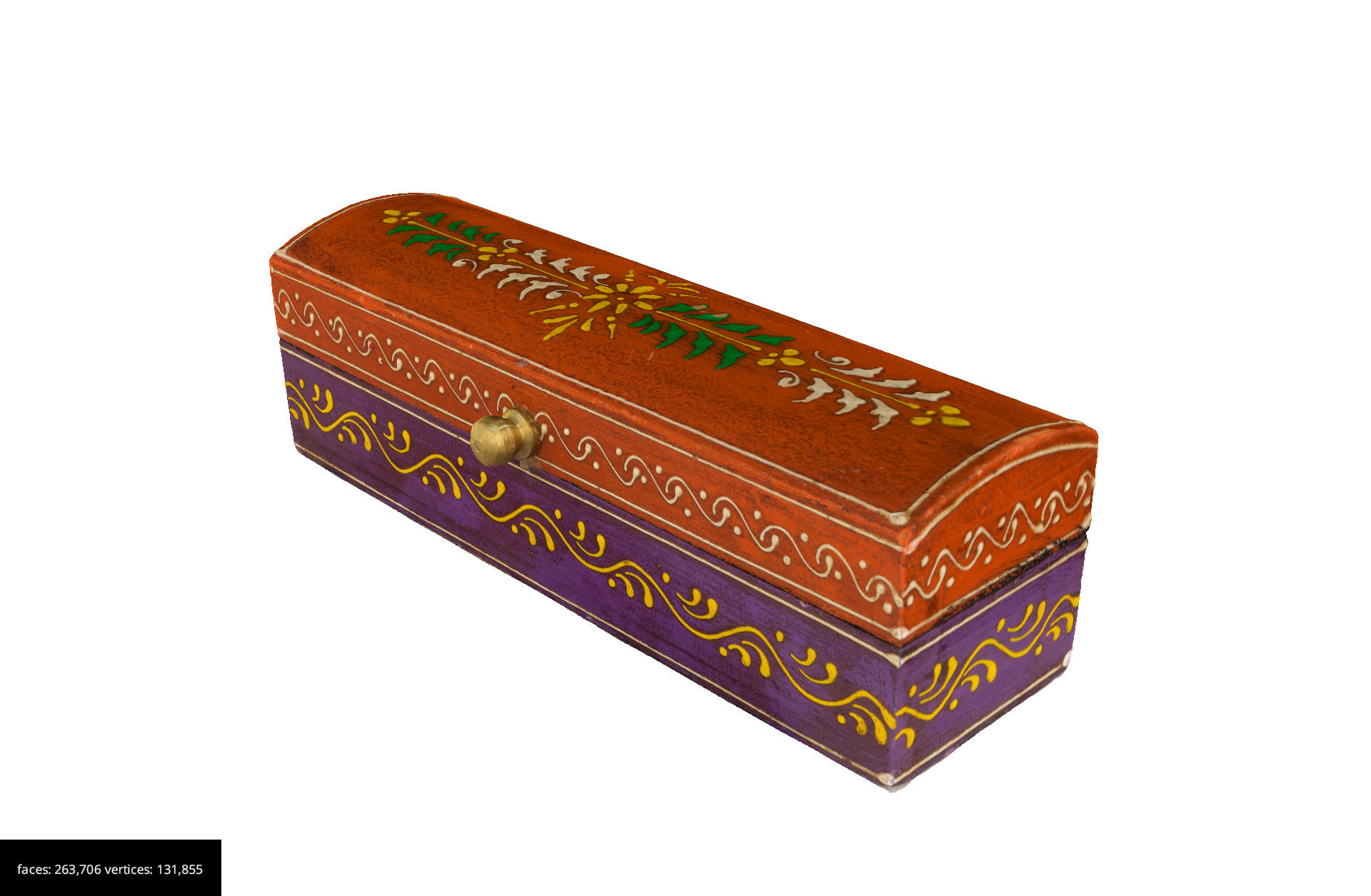
Step 10: Exporting the 3D model
At this point, we can export the 3D model.
Create another folder called “Exports” within your project folder and save the model in this folder.
It will be useful to export various 3D models at various resolutions. This will allow you to keep a high-resolution 3D model, while having a low-resolution 3D model for sharing and making available on the web.
It is good practice to name your models with information, for example:
ResourceIDofObjectifExistent_NameofObject_DateModelCreatedYY.MM.DD.[highres|medres|lowres]Go to Export in the menu and select Export Textured Mesh.
Select from the drop down, the name of your mesh.
Select from the drop down your preferred format and click Export.
To export the model at a lower resolution select your textured mesh in the right window “Textured Meshes”. Right Click on it and select Clone. A copy of your mesh will be created.
Go to Tools in the menu and select Mesh Filters > Decimation. You will be presented with the “Mesh decimation” window.
Select in the drop down menu the name of your cloned mesh. Select preserve boundaries and Apply Filter.
At this point, we need to regenerate the texture for the lower-resolution mesh. To do so we need to repeat the process above for generating the texture.
Go to Export in the menu and select Export Textured Mesh. Select in the drop down menu the name of your second mesh.
For web sharing GLTF is a good format to use. Select from drop down menu the format .glb or .gltf and click Export.
Challenge: Processing the photos and creating a 3D model
This activity can be done as a team
By using the images you captured during the lesson, use the software to create a 3D model.
Produce two versions: a high-resolution and a low-resolution and save on your PC.